BACK

Northern Colorado Area Plan – Ault to Cloverly Transmission Project

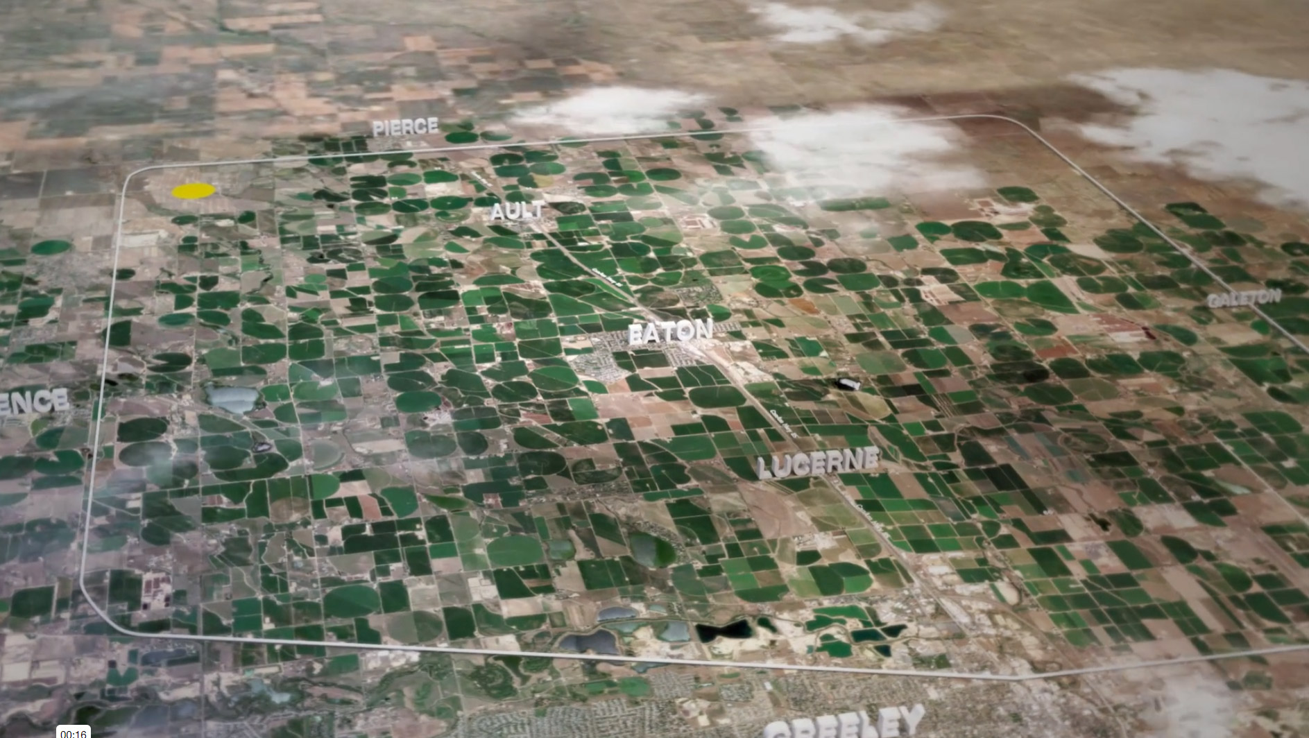
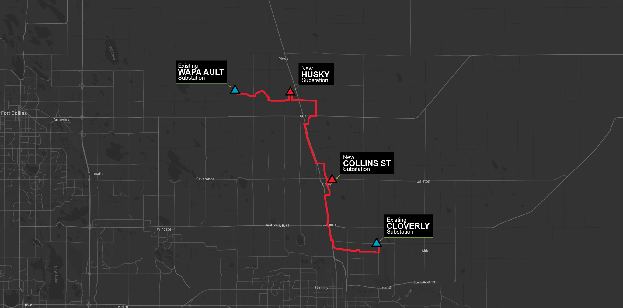
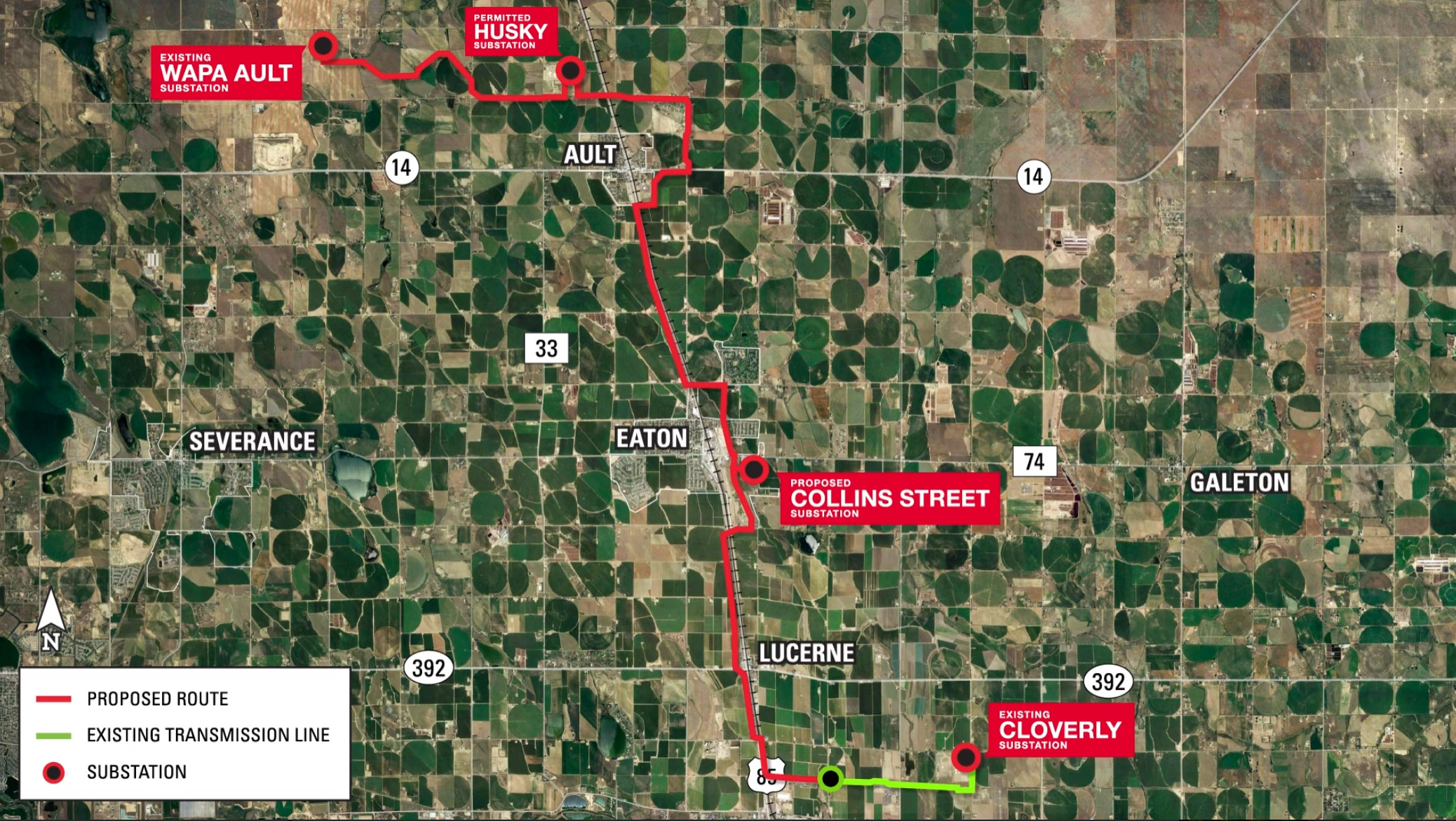
Map of the Northern Colorado Area Project (NCAP)

Project Overview

Xcel Energy continually invests in systems that strengthen the region’s electric system, improve service reliability and meet the current and future needs of customers across Colorado. The Northern Colorado Area Plan is part of our comprehensive, long-range plan and commitment to provide safe and increasingly clean electricity for all customers.

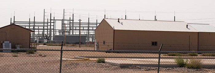
Xcel Energy is modernizing the electric system by replacing the existing 44 kilovolt (kV) transmission infrastructure with new, higher-voltage (115 kV and 230 kV) transmission lines between the Western Area Power Administration (WAPA) Ault Substation and Xcel Energy’s existing Cloverly Substation. The project also includes two new electrical substations and improvements to two existing substations. The planned improvements will reliably serve existing and future customers and meet growing and changing energy needs.

Project Updates

May 2022

Transmission line construction on all segments is complete, including nearly 20 miles of new 230 kV transmission infrastructure installed. Crews plan to energize the line later this summer, after substation construction is complete.

February 2019

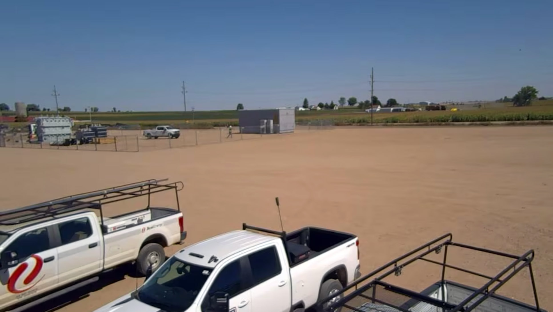
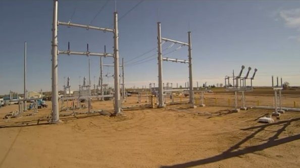
In February 2019, the Town of Ault approved the site plan for the Husky Substation to replace the existing Ault 44 kV Substation, which will be decommissioned after the Husky Substation is energized. Construction began on the Husky Substation in December 2021 and should be completed in late 2024.

The proposed Ault to Cloverly Transmission Project, another component of the Northern Colorado Area Plan, was approved by Weld County and the Town of Eaton in 2022 and construction will begin in spring 2023.

March 1, 2018

On March 1, 2018, the Colorado Public Utilities Commission approved the Certificate of Public Convenience and Necessity (CPCN) application for the Northern Colorado Area Plan. The CPCN approval allows Xcel Energy to move forward with the siting and permitting of project components included in the Plan.

Video Gallery

Project Need

                                                                                                                                        This project is part of Xcel Energy’s larger Northern Colorado Area Plan that will modernize the electrical system with higher-voltage transmission facilities. The project will increase our ability to serve existing and future customers, improve electric service reliability, and meet growing and changing energy needs.

Frequently Asked Questions

Transmission lines are a vital link used to deliver electricity over long distances from power sources (generation) to transmission substations closer to homes and businesses. A strong transmission system guarantees reliable electricity. Utilities connect their transmission systems to neighboring systems run by other utilities. These interconnected systems form regional grids that allow power to flow from one area to another, ensuring reliable and efficient electric delivery to customers, even during emergencies.

The flow of electricity cannot easily be controlled, and it cannot discriminate between generation sources. Instead, power follows the path of least resistance and carries power derived from diverse resources, such as wind, solar, natural gas, and coal.

Electricity also cannot be stored; it must be generated, transmitted, and distributed for immediate use. Traveling at almost the speed of light – 186,000 miles a second – electricity arrives where it’s demanded at almost the same time it’s produced.

Regional transmission organizations (RTOs) ensure reliable power supplies, adequate transmission infrastructure, and competitive wholesale electricity prices.

In Colorado, the Colorado Public Utilities Commission (CPUC) regulates utilities to ensure reliable electricity delivery.

Public Service Company of Colorado (PSCo, a subsidiary of Xcel Energy) provides electricity and natural gas to customers in Colorado. The service area of PSCo covers more than 8,200 square miles, with 4,615 miles of transmission.

In determining the need for a new or upgraded power line, utilities evaluate several factors. The primary factors are: (1) system capability to maintain adequate service, (2) system ability to serve projected load demand, and (3) system transfer capability to deliver new resources or provide emergency assistance to adjacent power systems.

Once the need for a facility has been established, several considerations determine where the power line is located and how long planning and construction will take. These considerations include existing system facilities, current and future land uses, terrain, environmental effects, economics, and landowner and public comments.

A combination of factors determine the eventual cost of construction of a new or upgrading an existing power line. While a straight-line path for a power line may be desirable, factors such as avoidance or mitigation of existing or planned land uses, avoidance or mitigation of environmental effects, the design required due to terrain, right-of-way acquisition, and others contribute to the siting and eventual costs of a project.

Overhead, high-voltage transmission lines are a reliable, low cost, easily maintained and established method to transport bulk electricity across long distances. In 2006, there were approximately 160,000 miles of 230 kilovolt (kV) or greater high-voltage transmission lines in the United States. The percentage of existing underground transmission is estimated at between 0.5 and 0.6 percent of this total. Line crews have a high performance and safety record at repairing and maintaining this extensive overhead infrastructure.
Burying high-voltage transmission lines may be appropriate in densely populated urban areas where required clearances are not available or in proximity to airports, or when sufficient right-of-way is not available for an overhead line.

Electric utilities consider the following factors when deciding whether to construct transmission facilities above ground or bury them.

  • Power Restoration. Damage to underground powerlines is difficult to pinpoint and repairs may take a few weeks to several months to complete. Damage to overhead lines is easy to locate and typically takes several hours or days to repair.
  • Capacity Requirements. Many cables are often required to match the capacity of the overhead circuit. Additional components increase the underground cost as a duct bank, vaults, splices, and terminations are required that also can reduce overall system reliability.
  • Line-length Challenges. High-voltage underground lines may require additional equipment to ensure proper electrical performance along the distance of the transmission line. The additional equipment translates to a higher overall cost, limits the length of the underground line installation, and increases the likelihood of failure because of additional components. A system study would be required to determine if this additional equipment would be required.
  • Multiple Cables and Cooling Options. Overhead lines are air cooled and widely spaced for safety. Underground cables are installed in concrete-encased PVC duct banks. Heat generated by the cables is dissipated into the earth.
  • Construction Impacts. Burying transmission lines results in more environmental impacts than placing them overhead. A 230 kV overhead line typically requires erecting structures and placing foundations every 800 to 1,000 feet. Typical structures are up to 120 feet tall, while the diameter of the foundation ranges from 5.0 to 8.0 feet. Burying a 230 kV double-circuit transmission line at a minimum would require a continuous trench or duct bank at least 3.5 feet wide at the bottom and 7.0 feet deep. Considerable clearing and grading would be necessary; dust and noise from construction would last three to six times longer than it would for overhead construction. Large concrete splice vaults or access structures are needed at 2,000- to 2,500-foot intervals. Permanent access to the vaults is required to make repairs when needed.
  • Easement and Land Purchase Requirement. An overhead line typically has a wider easement footprint than an underground line.
  • Life Expectancy. Underground high-voltage transmission lines have a life expectancy of 40+ years, while overhead lines have a life expectancy of more than 80 years.
  • Costs. An underground 230 kV line costs 10 to 15 times more than an overhead line due to time, materials, processes, the need to include transition substations, and the use of specialized labor. A proposed overhead double-circuit 230 kV line would cost $1 million per mile. Part of the added cost to bury lines may include routing and boring to avoid other underground installations, such as water, natural gas, and sewer lines. An overhead line often can be routed around or over these difficult areas.
  • Electric and Magnetic Fields. Electric and magnetic fields generally are greater directly over an underground installation (the earth does not provide shielding) and directly under an overhead installation. Magnetic fields tend to decrease more rapidly with distance from underground installations compared to overhead lines.
  • Noise and Lighting. Overhead high-voltage lines can emit hiss or hum noises. Underground lines are silent except in the immediate area near the transition substations, which are lighted throughout the night for security purposes.
  • Transition Stations. High-voltage underground transmission lines require small transition stations wherever the underground cable connects to overhead transmission. Transition stations require grading, access roads, storm water management facilities, and fencing.
  • Site Restoration. Site restoration for underground construction is a much larger endeavor than it is for overhead construction because soil is disturbed along the entire route. Top soils have to be restored and returned to vegetated areas, and all hard surface areas must be re-established to meet local codes. Vegetated areas may require up to two years to return to pre-construction conditions. Trees and large shrubs would not be allowed above the underground line due to potential problems with roots. In farmland or natural areas some herbaceous vegetation and agricultural crops may be allowed to return in the right-of-way.

When people talk about building new transmission lines, they often refer to an “easement” or a “right-of-way.” Although the terms are used interchangeably, they are distinct concepts.

An easement is a permanent right authorizing a person or party to use the land or property of another for a particular purpose. In this case, a utility acquires certain rights to build and maintain a transmission line. Landowners are paid a fair price for the easement and can continue to use the land for most purposes, although some restrictions are included in the agreement. An easement is the legal document that must be signed by the landowner before the utility can proceed.

A right-of-way is the actual land area acquired for a specific purpose, such as a transmission line, roadway or other infrastructure.

An easement is a land right document, and a right-of-way is the physical land upon which the facilities (transmission line, roadway, etc.) are located.

Terms of the easement are written in the easement agreement. Most electric utility easements are perpetual and not subject to termination or expiration. Once an easement is signed, it becomes part of the property record. The utility, landowner who signed the easement, and all future property owners, are bound by the agreement terms. If the utility removes the transmission line and abandons the right-of-way, it can release the easement rights.

Landowners typically are given a one-time payment based on fair market value for easement rights to their land, traditionally based on the appraised land value. Landowners also can elect to spread the payment out over time. The majority of land is still usable for the same purpose it had been used for, particularly in agricultural settings. Landowners also are eligible for reasonable compensation for property damage that may occur when the transmission line is constructed and during future repair and maintenance. Those issues are included in easement documents.

The landowner continues to pay property taxes on the right-of-way.

Utilities will require easements that allow for surveying, construction, operation, and maintenance of a transmission line across a defined right-of-way located on the landowner’s property. These easements will include the right to clear, trim, and remove vegetation and trees from within the right-of-way, as well as tall and dangerously leaning trees adjacent to the right-of-way that may threaten the line if they fall.

Xcel Energy designs, constructs, operates, and maintains its transmission lines and substation facilities to meet or exceed the requirements of the National Electric Safety Code (NESC), United States Department of Labor occupational safety and health standards, and our own power system safety standards. The company provides a maximum degree of safety and protection for the landowner and landowner’s property, the public, and our own employees.

There are land-use activities that are allowed on power line rights-of-way, if the activities do not interfere with operation and maintenance of the power line.

Normal farming activities are permitted if reasonable care is taken to prevent damage to power line structures from farm machinery. Lines are designed to allow safe operation of 14-foot-high (including antennas) farm machinery underneath the wires.

Machinery and Vehicle Guidelines

One of the most important rules to follow when working around power lines with tall equipment is simple. LOOK UP. Know where the power lines are and stay away from them.

Building or Planting Guidelines

The North American Electric Reliability Corporation (NERC) requires electric utilities to meet stringent requirements designed to keep our electric system safe and reliable, including standards for maintaining proper clearances. It is the utility’s responsibility to keep a certain amount of distance around power lines clear of anything that may make contact or near-contact with a power line. This includes buildings and incompatible vegetation.

Trees or other vegetation that could grow into or fall across the conductors may have to be trimmed, topped, or removed. You must call your utility provider before planting any trees or shrubs, or building any structures in power-line right-of-way areas to help avoid problems in the future.

Fence guidelines

Fence wires mounted on weed posts can build up an electrical charge near power lines. Important factors are:

  • Length of fence paralleling the power line.
  • Distance between the power line and the fence.
  • Amount of moisture in the fence posts and the ground.
  • Presence of grounding devices such as metal fence posts or weeds growing next to the fence.

Irrigation and Watering Guidelines

The potential for water and metal to conduct electricity makes it important to take safety precautions when irrigating near power lines. Additionally, fertilizers and pesticides tend to increase conductivity of water, making extra precautions necessary. Watering the lawn at your home or business is not problematic; however, you still must prevent a direct, solid stream of water from contacting the power line.

Recreation Guidelines

Safe Construction and Maintenance Practices

Birds and Power Lines

Xcel Energy uses several strategies to reduce the number of birds that are injured or killed when they contact power lines or electrical equipment. The strategies are:

  • Preventive – conducting risk assessments and using avian-safe standards where possible.
  • Reactive – documenting mortalities, notifying resource agencies, and applying remedial measures where appropriate.
  • Proactive – educating employees and being involved in organizations that conduct avian interaction research.

For additional information regarding birds and power lines, visit the Avian Power Line Interaction Committee website at www.aplic.org.
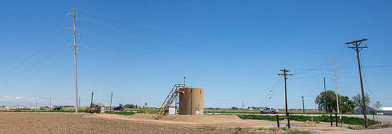
If you are considering operating a vehicle within a height greater than 14 feet, contact your local utility company. Call first, even if it appears the line has clearance exceeding 14 feet. And always remember:

  • Physical contact with power lines is extremely hazardous and can cause a lethal shock. Equipment SHOULD NOT be operated under a power line in a manner that causes contact or near-contact with the wires.
  • DO NOT lift, elevate, or pass under a power line any object, tool, or vehicle that could make contact or near-contact with the wires.
  • To help prevent arc flashing, or an explosion, it is recommended that equipment, antennas, and people stay at least 14 feet away from any energized power line.

Fueling vehicles or equipment under power lines is not recommended. If you must fuel a vehicle or equipment under a power line, use a non-metallic or plastic container. The vehicle also should be grounded to eliminate any source of sparks.

For your benefit, DO NOT plant any trees or shrubs in the right-of-way area before talking to the utility first. As a landowner, even with an easement granted, most property rights do not remain with the landowner, but a utility doesn’t want to be forced to remove a tree planted in the right-of-way area. Activities in the easement area that do not interfere with the safe construction, operation, and maintenance of the power line are permitted, i.e., using the land for pasture, farming, or gardening.

Not without written approval from the electric utility. Buildings and other structures generally are not permitted on rights-of-way. It is important that you discuss projects with the utility in order to avoid creating situations that could become unsafe to the landowner and/or utility workers.

Non-electric fences made of barbed wire or similar materials directly attached to and near a power line, use at least one steel post every 150 to 200 feet to ground the fence.

Electric fences, being specially insulated from the ground, can pick up a charge from power lines. Usually, the charge will drain off when the charger unit is connected to the fence; however, when the charger is disconnected either for maintenance or when the fence is being built, a small shock may be produced. Call Xcel Energy for assistance. Typically, symptoms such as shock can be prevented by:

  • Shorting out one or more of the fence insulators to the ground with a wire when the charger is disconnected, or
  • Installing an electric filter that will ground charges induced from a power line while still allowing the charger to be effective. Again, contact Xcel Energy for assistance if you have questions—every situation is unique.

Yes, as long as you take these precautions:

  • Prevent a solid stream of water from hitting the wires. Equipment with nozzles that are small in diameter or spray a fine mist typically is not problematic because the solid part of the water stream will not reach the power line wires. Also, an intermittent spray of water will not conduct significant amounts of electricity. Even large-diameter nozzles operating at their normal spray angle typically will not reach the wires with a solid stream. However, at no time should the solid part of a water steam touch power-line wires. Should that happen, turn the water off by switching the pump off before trying to correct the problem.
  • Make sure the irrigation system is well grounded. If you have questions as to whether or not your irrigation system is adequately grounded, call your local electric utility.
  • Check with utility before installing a new irrigation system. Each system should be reviewed on a case-by-case basis; questions about the installation and operations of an irrigation system adjacent to or under a power line should be directed to your electric utility.
  • DO NOT install long lengths of pipe parallel and adjacent to power lines. They should be laid out at right angles to power lines, if possible, to reduce risk of pipes building up an induced charge.
  • Be careful when moving the pipelines. When loading irrigation pipelines, stay at least 50 feet from power lines to avoid any chance of raising them too close to the wires.

No. Here are some easy rules to follow:

  • Do not fly kites or model airplanes near any power line.
  • Always fly kites and model planes so the wind carries then away from power lines, and television or radio antennas.
  • Call your electric utility if a kite or plane becomes snagged in a power line. DO NOT pull the string or climb a power-line structure, pole, or ladder to get it down.
  • If a model airplane is caught in the power line, let go of the control line immediately and call your electric utility for assistance.
  • DO NOT attempt to retrieve it yourself.

Hunting is allowed near and under a power line, if you are the landowner. Intentionally shooting at power lines is illegal. Shooting insulators or conductors can break a wire or cause hazards such as an electrical discharge or arc through the air.

No. Fires should not be started under a power line. Smoke and hot gases from fires can create a conductive path for electricity.

  • A fire could damage the poles or wires and result in an outage.
  • It is possible that the power line could flash to the ground through hot air and smoke, which is a serious safety hazard.

Transmission lines are built and maintained to meet or exceed safety standards specified by the National Electric Safety Code (NESC) and the North American Electric Reliability Corporation (NERC). Every effort is made to ensure safety in construction, operation, and maintenance of power lines. For information on safe distances for specific activities near power line infrastructure, contact the utility operating the power line. Power lines and line infrastructure are designed to withstand extreme weather conditions. Protective devices at powerline terminals stop the electricity flow under abnormal operating circumstances.

Xcel Energy follows strict power line maintenance standards. Power lines are inspected regularly (usually during fall or winter months) and by air to look for the following:

  • Non-compatible vegetation and hazards within the right-of-way.
  • Equipment needing repair or replacement.
  • Right-of-way encroachments, which can be hazardous to safety and reliable operations.
  • Anything that might jeopardize safe, reliable operation of the power line.

Utilities must visit the right-of-way for these inspections, but visits may be minimal, and landowners will be contacted prior to inspections or maintenance. However, in cases of emergency, advance contact may not be possible.

Transmission line structures and equipment can be attractive to birds for roosting and building nests. Utilities try to minimize the risk of electrocution or injury to birds, of damage to electrical equipment, and outages to customers that may result when birds come in contact with power lines and structures. Perch discouragers are used to try to keep birds from perching or roosting on utility equipment. Nest management programs include installing nest boxes or platforms in safe areas on or near structures, where warranted. Additionally, utility personnel are educated on nest reporting, nest removal, and platform construction.

Electrocution of birds typically is not associated with transmission lines greater than 138 kilovolts (kV) because generally the electrical components are separated enough that a bird can avoid contact with two of them, which would fatally complete a circuit. Problems that do arise can be corrected in two primary ways:

  • Isolation – moving the components farther apart to get the necessary clearance.
  • Insulation – using covers on various electrical components to prevent contact with the component that would cause the electrocution.

There are measures that can be taken before construction and after construction.

Pre-construction efforts

  • Use vegetation, topography, or man-made structures to shield lines.
  • Cluster lines together.
  • Site lines away from obvious flyways if possible.

Post-construction efforts

  • Modify habitats.
  • Create habitats on the same side of the power line to minimize crossings.
  • Minimize human activities/disturbances near the line (educational process).

Marking lines

Marking lines with various types of markers can decrease but not eliminate bird collisions. The different types of markers vary in effectiveness. Devices include bird and swan flight diverters and clamp-on markers. Xcel Energy has used a variety of these markers on its lines. The decision to use them is based on:

  • Effectiveness
  • Line voltage rating
  • Weight of markers
  • Wind/ice loading factors
  • Durability
  • Ease of installation
  • Effect on the viewshed
  • Susceptibility to vandalism

Electric fields are created by voltage. The voltage on an electric wire is caused by electric charges that can exert force on other nearby charges. Electric fields are found near any electric device that is plugged in, even if it not operating. For instance, plugging an appliance such as a lamp or hair dryer into a wall socket applies the voltage to the cord, which is then surrounded by an electric field. Electric fields are strongest closest to the source, and the higher the voltage the stronger the field.

Magnetic fields are created by current. When charges move they produce an electric current that can exert forces on other electric currents. For instance, turning on an appliance, such as a lamp or hair dryer creates a flow of current, which causes a magnetic field. Magnetic fields are strongest closest to their source and are higher when more current is drawn.

EMF can neither be seen nor felt. Generally, humans appear to be unable to sense or detect low levels of EMF. The currents induced in people from household wiring or power line EMF are too weak to be felt. They are measured in millionths of an ampere. Strong fields, such as those directly under high-voltage transmission lines, can cause the hair on a person’s head and arms to become charged enough to be perceived.

EMF is found everywhere electricity is used. Household appliances such as hair dryers, electric blankets, and blenders produce EMF. Office equipment such as computers and copy machines produce EMF. Even the earth has its own magnetic field. In normal everyday life, it is impossible to avoid electric and magnetic field exposure. EMF is everywhere in our environment and occurs in nature as well. Field levels from household appliances and office equipment are about the same or greater than those fields found near power lines.

Radio waves, microwaves, and X-rays are different and more powerful forms of electric and magnetic energy and should not be confused with the power frequency EMF addressed here.

Anything that generates, distributes, or uses electricity creates EMF. Figure 1 is a list of some appliances and machines commonly found in homes or offices and the magnetic field levels found nearby.

We also encounter a wide variety of EMF in other ways―natural and man-made. The earth’s atmosphere creates slowly varying electric fields, and thunderstorms produce very intense electric fields that are occasionally discharged by a lightning bolt. The earth’s core produces a steady magnetic field, as can easily be demonstrated with a compass needle which points to magnetic north. This magnetic field has a strength of about 550 milligauss (mG).

Magnetic fields from the earth or from small magnets exert forces on electric currents or on other magnetic objects, as when a compass needle points toward a nearby magnet. Magnetic fields are common in our lives. Many children’s toys contain magnets and many of us use refrigerator magnets, generating fields of about 100,000 to 500,000 mG.

An increasingly common diagnostic procedure, magnetic resonance imaging (MRI), uses fields of about 20,000,000 mG. If you were to spin a magnet at a rate of 60 times a second, you would get an alternating magnetic field like the fields produced by power lines.

Figure 1. Typical 60 hertz magnetic field levels from some common home appliances

Magnetic field 6 inches from appliance (mG) Magnetic field 2 feet away (mG)
Electric shaver 100 -
Vacuum cleaner 300 10
Electric oven 9 -
Dishwasher 20 4
Microwave oven 200 10
Hair dryer 300 -
Computers 14 2
Flourescent lights 40 2
Faxogram machine 6 -
Copy machines 90 7
Garbage disposals 80 2

Source: National Institute of Environmental Health Services/National Institutes of Health: EMF Associated with the Use of Electric Power

Field strength depends on the amount of current flowing through the device and the voltage level. Fields are strongest immediately surrounding an electric wire or device. Field levels rapidly weaken as you move farther from the source. Electric fields are measured in units of volts per meter, while magnetic fields are measured in gauss or milligauss (1/1,000 gauss).

You can monitor your daily exposure to magnetic fields by wearing a personal exposure meter (called a magnetometer or gauss meter) or by keeping one close to you. This is the most accurate way to measure your true exposure to magnetic fields during the course of your normal activities. Other meters can be put in a location – like your kitchen or home office―to measure typical EMF levels in that spot. This type of measurement isn’t an accurate measure of personal exposure, however, because it doesn’t take into account your distance from the source of the fields or the amount of time you might spend in that place. Contact your local electric service provider. Most utilities offer a free measurement service to customers to measure magnetic fields in their homes or businesses.

Exposure levels vary from individual to individual and from home to home, but a study by the Electric Power Research Institute (EPRI) puts the background levels of power line magnetic fields in the typical United States home at between 0.5 mG and 4 mG with an average of 0.9 mG. Levels rise the closer you get to the source of the field. Most people are exposed to greater magnetic fields at work than in their homes. See Figure 1.

Figure 1. Typical 60 hertz magnetic field levels from some common home appliances

Magnetic field 6 inches from appliance (mG) Magnetic field 2 feet away (mG)
Electric shaver 100 -
Vacuum cleaner 300 10
Electric oven 9 -
Dishwasher 20 4
Microwave oven 200 10
Hair dryer 300 -
Computers 14 2
Flourescent lights 40 2
Faxogram machine 6 -
Copy machines 90 7
Garbage disposals 80 2

Source: National Institute of Environmental Health Services/National Institutes of Health: EMF Associated with the Use of Electric Power

All transmission lines produce EMF. The fields are the strongest directly under the lines and drop dramatically the farther away you move. These magnetic fields will change with the amount of electricity flowing on the line that varies with the time of day and the season of the year. Xcel Energy builds transmission lines according to rules set by the Colorado Public Utilities Commission, of 150 mG or less. Contact your local utility to find out EMF information about a particular transmission line near you.

Because magnetic fields are not shielded by ordinary materials, burying power lines won’t keep the fields from passing through the ground. In fact, underground lines can produce higher levels of magnetic fields directly above the line at ground level because these lines are located closer to you (5 feet below) compared to overhead lines (25 to 30 feet above). However, the strength of the magnetic field from underground lines falls away more quickly to the side with distance than from overhead lines because of the way the lines are built.

Compared to overhead lines, underground lines are significantly more expensive to install (up to 10 to 20 times more expensive), more difficult to repair and can have greater environmental impacts because of the disturbance of the soil to install the underground lines. Since recent research results provide no conclusive connection between EMF exposure and health effects, burying lines isn’t a reasonable alternative.

There are no federal standards limiting residential or occupational EMF exposure. Several states have set standards for the allowed level of magnetic fields from new power lines. The Colorado Public Utilities Commission has determined that magnetic fields for new power lines of 150 mG or less are reasonable at the edge of the right-of-way. Other states have established similar standards of 150 to 200 mG for new transmission power lines.

The EMF levels produced by appliances vary from manufacturer to manufacturer and model to model. The designs of many newer model appliances, in general, often produce lower fields than older models. An example is electric blankets where new blankets produce much lower fields than those produced 20 years ago. There is no federal certification program on EMF levels so beware of advertisements on appliances making claims of federal government certification of low or zero EMF levels.

The issue has been studied for more than 40 years by government and scientific institutions around the world. The balance of scientific evidence indicates exposure to EMF does not cause disease.

EMF Sources and Useful Links

The following are links to more information (and Denver area) studies on electric and magnetic fields:

  • The National Institute of Environmental Health Services (NIEHS) offers information on a variety of EMF topics. In June of 2002 they prepared EMF: Electric and Magnetic Fields Associated with the Use of Electric Power, Questions and Answers. This booklet, along with other helpful links, can be found at www.niehs.nih.gov/health/topics/agents/emf/.
  • Electric and Magnetic Fields: Facts, Western Area Power Administration www.wapa.gov/newsroom/pdf/emfbook.pdf
  • “Electromagnetic fields and public health,” World Health Organization fact sheet, www.who.int/mediacentre/factsheets/fs322/en/index.html. More general information on EMF can be found at www.who.int/peh-emf/en/.
  • “Unproven Risks – Non-Ionizing Radiation” (2008), The American Cancer Society. www.cancer.org/docroot/NWS/content/NWS_2_1x_The_Environment_and_Cancer_Risk.
  • Wertheimer, N and E Leeper, 1979. Electrical wiring configurations and childhood cancer. American Journal of Epidemiology, Volume 109, pages 273-84.
  • Savitz, D, H Wachtel, F Barnes, E John and J Tvrdik, 1988. Case – control study of childhood cancer and exposure to 60 Hz magnetic fields. American Journal of Epidemiology, Volume 128, pages 21-38.
  • Pearson, R and L Zaffanella, 2003. Association of residential magnetic fields with contact voltage; measurements in 191 Denver area homes. Electric Power Research Institute, Palo Alto, CA, Technical Report 1005569.

High levels of power line EMF can interfere with a pacemaker’s ability to sense normal electrical activity in the heart. Most often, the electric circuitry in a pacemaker might detect the interference of an external field and direct the pacemaker to fire in a regular, life-preserving mode. This isn’t considered hazardous and actually is a life-preserving default feature. There have been cases with dual-chamber pacemakers triggering inappropriate pacing before the life-preserving mode takes over. Newer pacemakers have been designed to be less susceptible to this type of interference.

The American Conference of Governmental Industrial Hygienists (ACGIH) issued guidelines for EMF exposure for workers with pacemakers or implantable defibrillators. Maximum safe exposure for workers with these medical devices at 60 hertz (the frequency of most transmission lines) is 1.0 G (1,000 mG) for magnetic fields and 1.0 kilovolt per meter for electric fields. Non-electronic metallic implants (artificial limbs, screws, pins, etc.) can be affected by high magnetic fields like those produced by MRI devices but are generally unaffected by the lower magnetic fields produced by most other sources.

If you wish to reduce EMF levels in your vicinity, you can do so by recognizing that your exposure is determined by the strength of the magnetic fields given off by things around you, your distance from the source of the field, and how much time you spend in the field. Creating distance between yourself and the sources of EMF is the easiest way to reduce exposure. Standing back―even an arm’s length away―from appliances that are in use is a simple first step. Remember, EMF decreases dramatically with distance. This is more feasible with some appliances than with others, but the following simple recommendations will help you reduce your EMF exposure at home:

  • Move motor-driven electric clocks or other electrical devices away from your bed.
  • Be aware that electric motors change electricity into mechanical energy by using magnetic fields, so any motorized appliance (e.g., hairdryers, shavers, fans, vacuum cleaners, air conditioners) will produce magnetic fields.
  • Stand away from operating appliances that use a lot of electricity.
  • Sit a few feet away from the television and at least an arm’s length from the computer screen. Liquid crystal or plasma displays (LCDs), however, produce very low levels of EMF compared to the older cathode-ray tube (CRT) displays.
  • Limit the time you’re exposed to a magnetic field by turning appliances, like computer monitors, off when you’re not using them.

Although conclusive results on the potential for health effects from EMF are not yet known, utilities typically take prudent actions in response to concerns about EMF. For example:

  • Xcel Energy continues to financially and technically support and participate in scientific research on EMF and monitor results of research activities by utility, government, and private groups.
  • Xcel Energy gathers and shares emerging information on EMF and communicate openly and honestly with the public on EMF matters.
  • Xcel Energy investigates alternative design and siting approaches for and upgradeding transmission facilities to reduce public exposure to EMF, particularly when facility siting may occur in populated areas.

EMF Sources and Useful Links

The following are links to more information (and Denver area) studies on electric and magnetic fields:

  • The National Institute of Environmental Health Services (NIEHS) offers information on a variety of EMF topics. In June of 2002 they prepared EMF: Electric and Magnetic Fields Associated with the Use of Electric Power, Questions and Answers. This booklet, along with other helpful links, can be found at www.niehs.nih.gov/health/topics/agents/emf/.
  • Electric and Magnetic Fields: Facts, Western Area Power Administration www.wapa.gov/newsroom/pdf/emfbook.pdf
  • “Electromagnetic fields and public health,” World Health Organization fact sheet, www.who.int/mediacentre/factsheets/fs322/en/index.html. More general information on EMF can be found at www.who.int/peh-emf/en/.
  • “Unproven Risks – Non-Ionizing Radiation” (2008), The American Cancer Society. www.cancer.org/docroot/NWS/content/NWS_2_1x_The_Environment_and_Cancer_Risk.
  • Wertheimer, N and E Leeper, 1979. Electrical wiring configurations and childhood cancer. American Journal of Epidemiology, Volume 109, pages 273-84.
  • Savitz, D, H Wachtel, F Barnes, E John and J Tvrdik, 1988. Case – control study of childhood cancer and exposure to 60 Hz magnetic fields. American Journal of Epidemiology, Volume 128, pages 21-38.
  • Pearson, R and L Zaffanella, 2003. Association of residential magnetic fields with contact voltage; measurements in 191 Denver area homes. Electric Power Research Institute, Palo Alto, CA, Technical Report 1005569.

Project and Construction Details

What You Can Expect During Construction

In the early stages of construction, Xcel Energy employees and contractors will work within and around the utility’s right-of-way to perform field assessments and gather information that’s used to refine the vegetation and construction plan and minimize disturbance. Survey stakes and flagging will clearly mark easement boundaries and pole locations. Work zones will provide safety barriers for construction crews and the public. Vegetation and other obstacles, such as fences and objects that impede construction, are temporarily removed or relocated within or along the edge of the easement to allow for the safe construction, operation and maintenance of the transmission line.

Vegetation trimming, pruning and removal are conducted in two phases as the project progresses. The initial phase includes removing incompatible vegetation in and around the transmission line easement. This may include vegetation outside the easement that could pose a risk, such as dead or unstable trees that are close enough to strike a line or pole if they fall. After the transmission line is built and conductor is in place, a final vegetation assessment is performed to verify proper clearance.

We take thoughtful measures to protect yards and agricultural property around our construction area by installing temporary erosion-control measures to minimize ground disturbance and keep sedimentation, from potential stormwater runoff, from leaving the construction site. We also place composite mats or riprap to stabilize the ground at right-of-way entry points and silt fences, wattles and haybales along the right-of-way to control sediment runoff.

Large, heavy equipment, including cranes, excavators, flat bed trailers and bucket trucks, are used to construct and install new structures and conductor. On occasion, we may need to temporarily stop traffic to facilitate the safe delivery of materials and equipment on and off the jobsite, but these disturbances typically last only a few minutes.

Crews work to keep the project on schedule by concurrently working in multiple areas along a line segment. As a result, you may notice lulls in construction activity near your home while crews work in other locations. We strive to be a good neighbor, respecting local noise ordinances and working to limit noise-producing construction activities outside of normal business hours of 8 a.m. to 5 p.m. Local noise ordinances allow construction between the hours of 7 a.m. and 9 p.m. On occasion, our crews need the flexibility to work outside those hours to complete time-sensitive activities.

When construction is completed, inspections are conducted and restoration begins. The right-of-way will be cleared of construction materials and equipment and restoration activities will be performed.

We do not anticipate any disruption in your electric service during construction. However, unforeseen circumstances do arise at times and we must adjust our plans. Should a temporary outage become necessary to perform a portion of the work, Xcel Energy will notify you in advance.

Construction Progress and Activities

Description

Build 4.4 miles of 230 kV double-circuit transmission line from the Western Area Power Administration (WAPA) Ault Substation to the new Xcel Energy Husky Substation. This transmission line will accommodate two, 230 kV circuits; however, only one circuit will be installed until additional electrical service is needed. Install fiber optic ground wire (OPGW) for length of the line.

The new Husky Substation will replace the Xcel Energy Ault 44 kV Substation, scheduled for decommissioning in summer 2024.

Construction Updates

Transmission line construction completed in the summer of 2023. Xcel Energy will collaborate with the Western Area Power Administration (WAPA) to connect Segment 1 to the WAPA Ault substation in the summer of 2024. The new transmission line will be energized once work at each substation is completed.

Description

Build 8.8 miles of new 115/230 kV double-circuit transmission line from the new Husky Substation to the new Collins Street Substation. This transmission line will accommodate one 115 kV circuit and one 230 kV circuit; however, only the 115kV circuit will be installed until additional electrical service is needed. Installation will include fiber optic ground wire for the length of the line.

Construction Updates

Transmission line construction completed in February of 2024. Physical construction is complete at Husky Substation. Crews will continue to install/connect cable and control-work components through the summer of 2024. The new transmission line will be energized once work at each substation is completed.

Description

Build 5.9 miles of new 115/230 kV double-circuit transmission line from the new Collins Steet Substation to the Cloverly Tap near 31510 County Road 41. This transmission line will accommodate one 115 kV circuit and one 230kV circuit; however, only the 115 kV circuit will be installed until additional electrical is needed. Installation will include fiber optic ground wire for the length of the line.

Construction Updates

Transmission line construction completed in April of 2024. Work at the Collins Street Substation began in April 2023. Grading, foundations, and physical construction are complete. Crews will continue to install/connect cable and control-work components through the summer of 2024. The new transmission line will be energized once work at each substation is completed.

Description

Remove 1.01 miles of existing 44kV transmission line conductor and replace with new 115 kV conductor from the Cloverly Tap near 31510 County Road 41 to Weld County Road 43. Various equipment upgrades will take place inside the fence at the existing Cloverly Substation.

Construction Updates

Transmission line construction completed in April of 2024. Physical construction upgrades at the Cloverly Substation were completed in October of 2023 and activities inside the substation’s control house will continue through the summer of 2024. The new transmission line will be energized once work at each substation is completed.

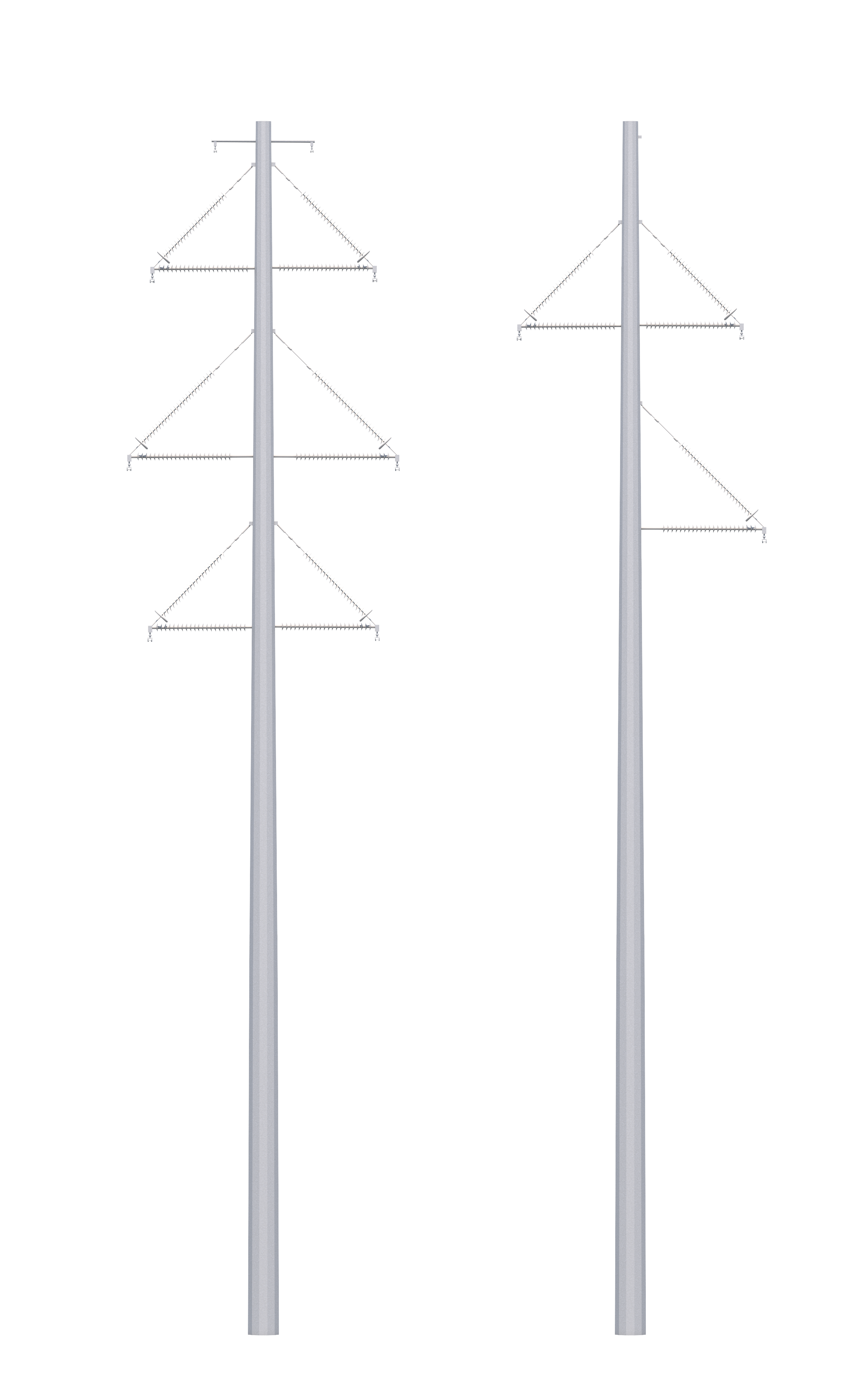
Typical Structures

Steel Monopole
Two types of steel monopoles

Project Construction Schedule

  • Husky Substation: January 2023 - Summer 2024
  • Collins St. Substation: Spring 2023 - Summer 2024
  • Segment 1: Wapa Ault - Husky: Summer 2023 - Fall 2023
  • Segment 2: Husky - Collins St.: Summer 2023 - Winter 2024
  • Segment 3: Collins St. - Cloverly Tap: January 2024 - Spring 2024
  • Segment 4: Cloverly Tap Reconductor: January 2024 - Spring 2024

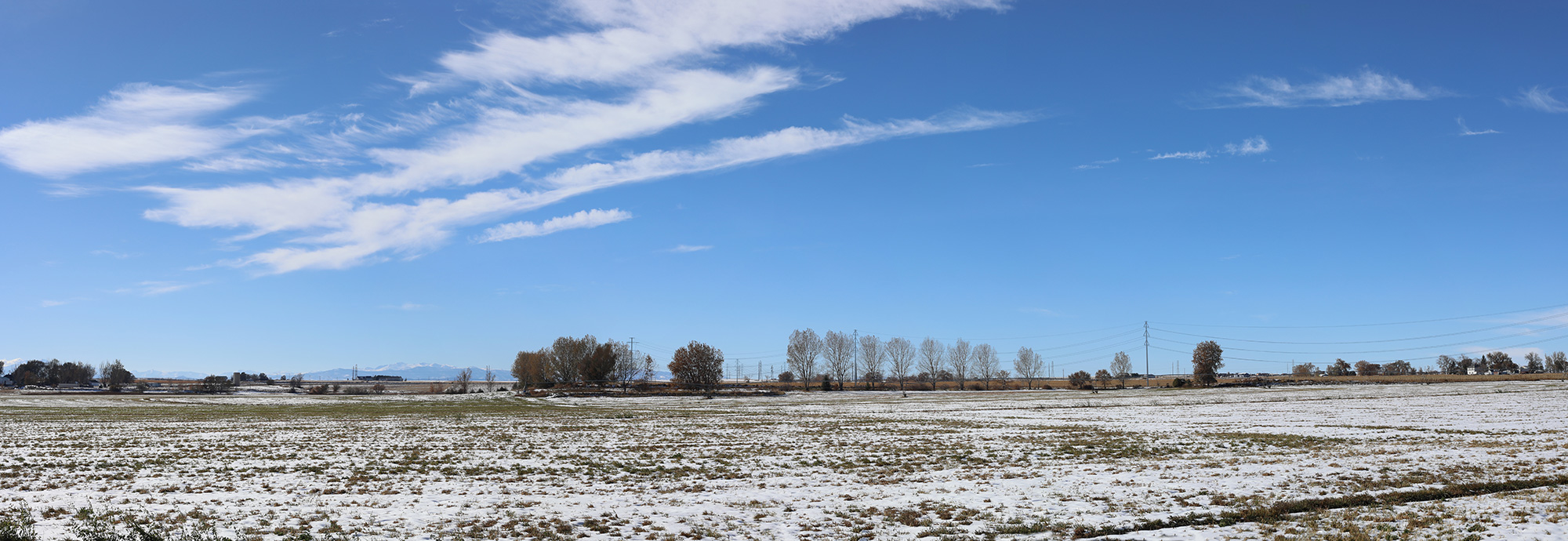
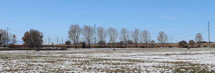
Photo Simulations

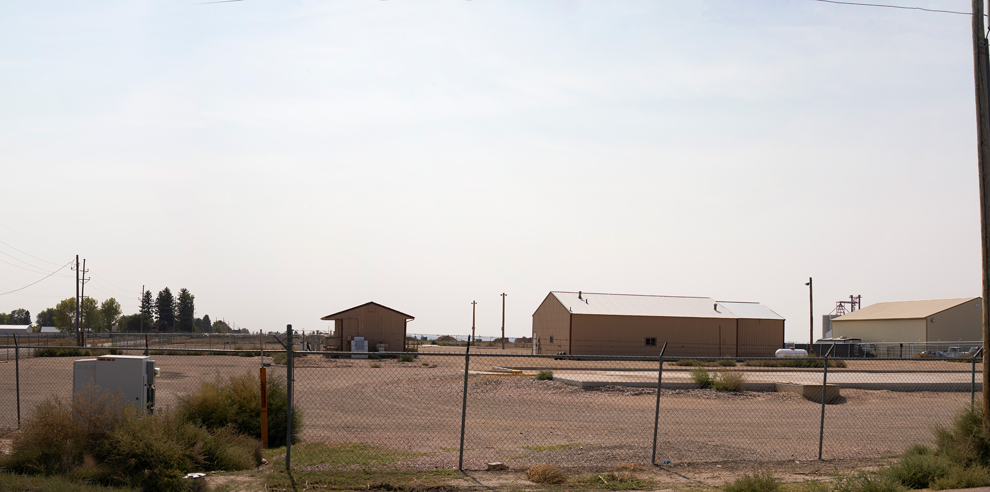
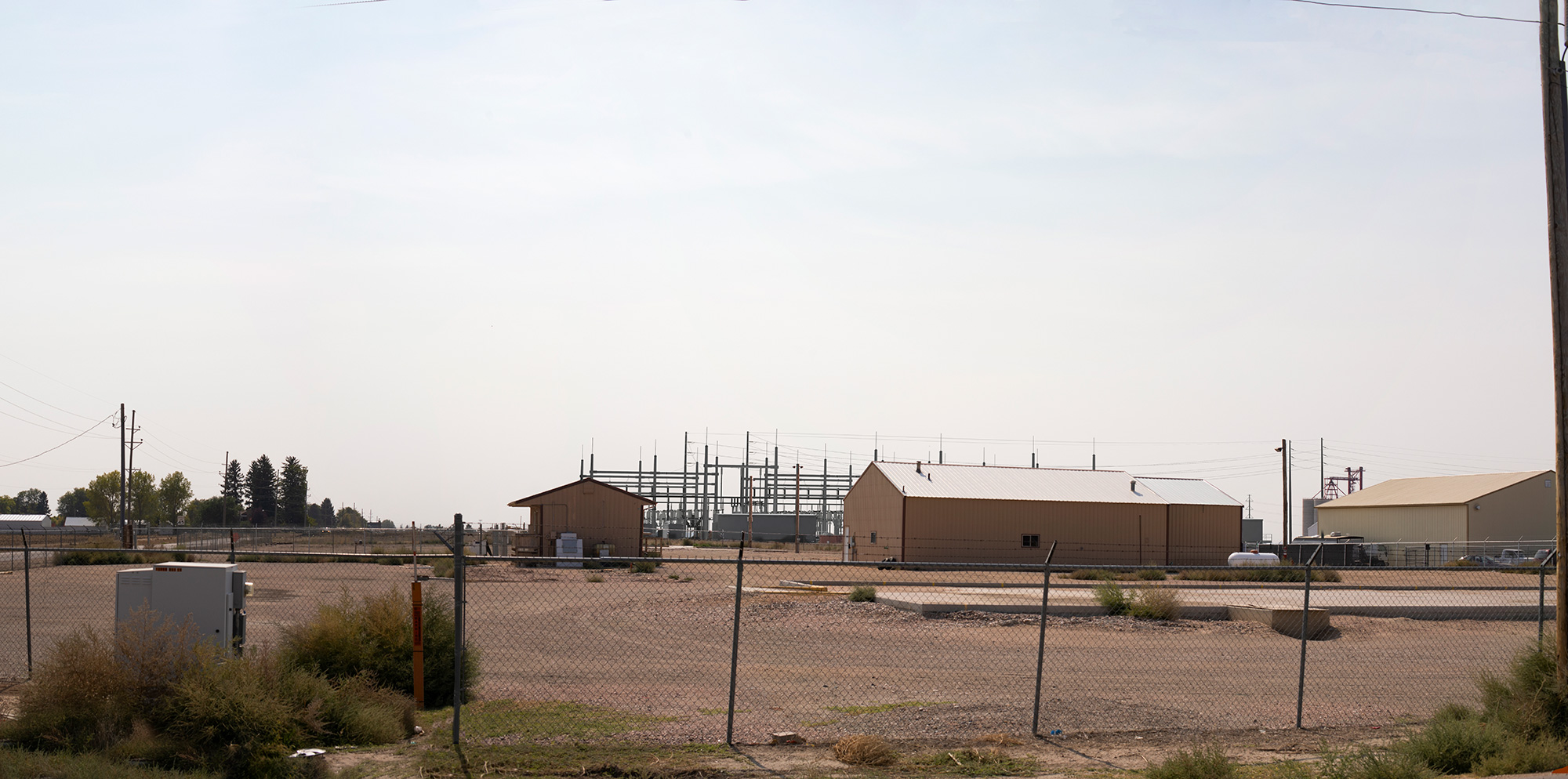
Simulation 1
28/10/2020
12:49 PM
Looking: West
County Roads 84 and 86
*Photo simulations are for discussion purposes only and may change pending public, regulatory, and utility review.
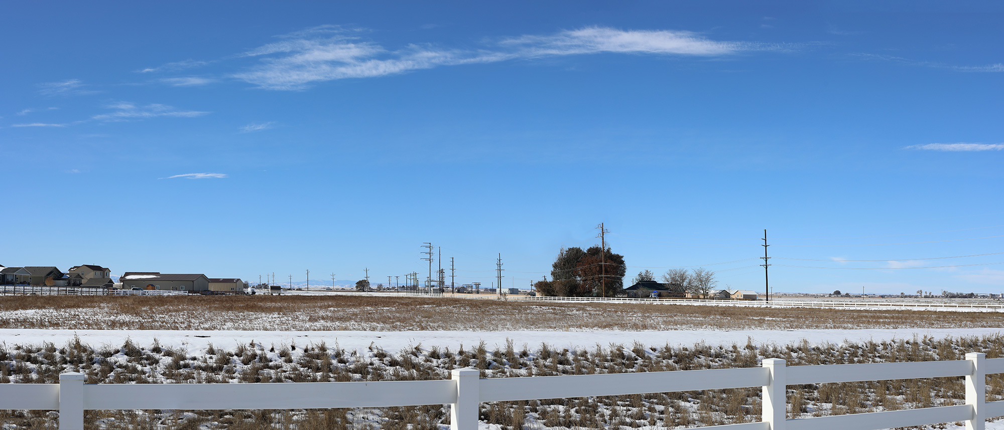
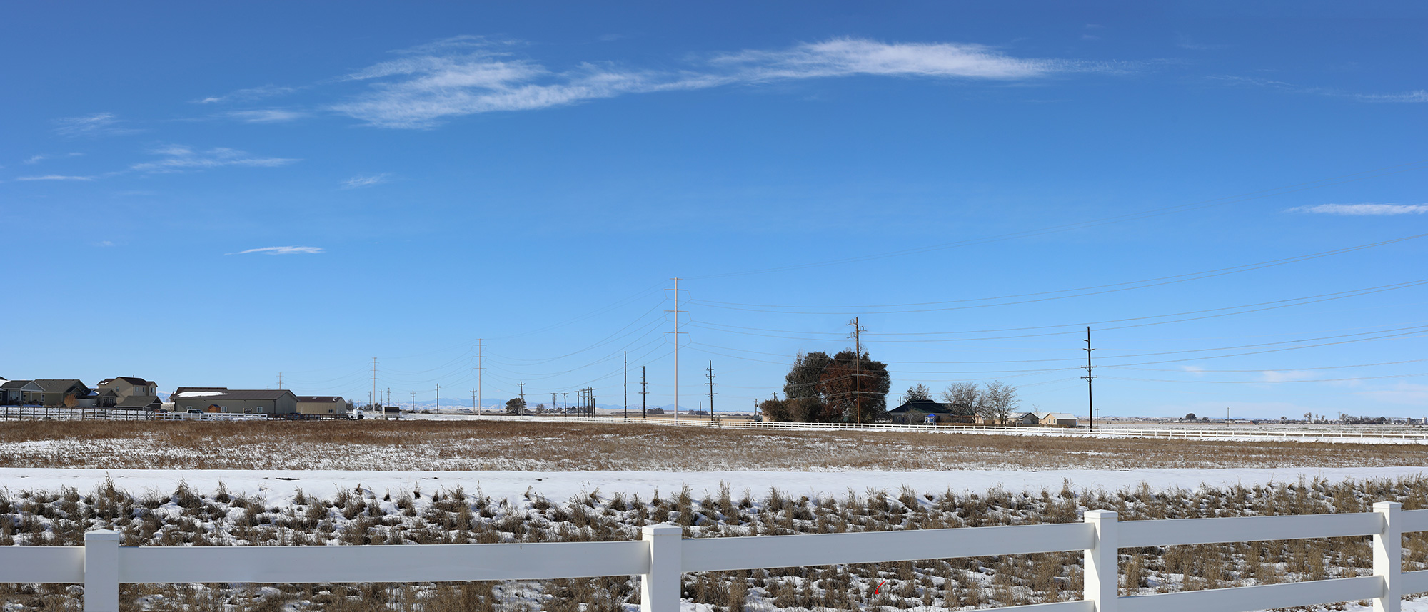
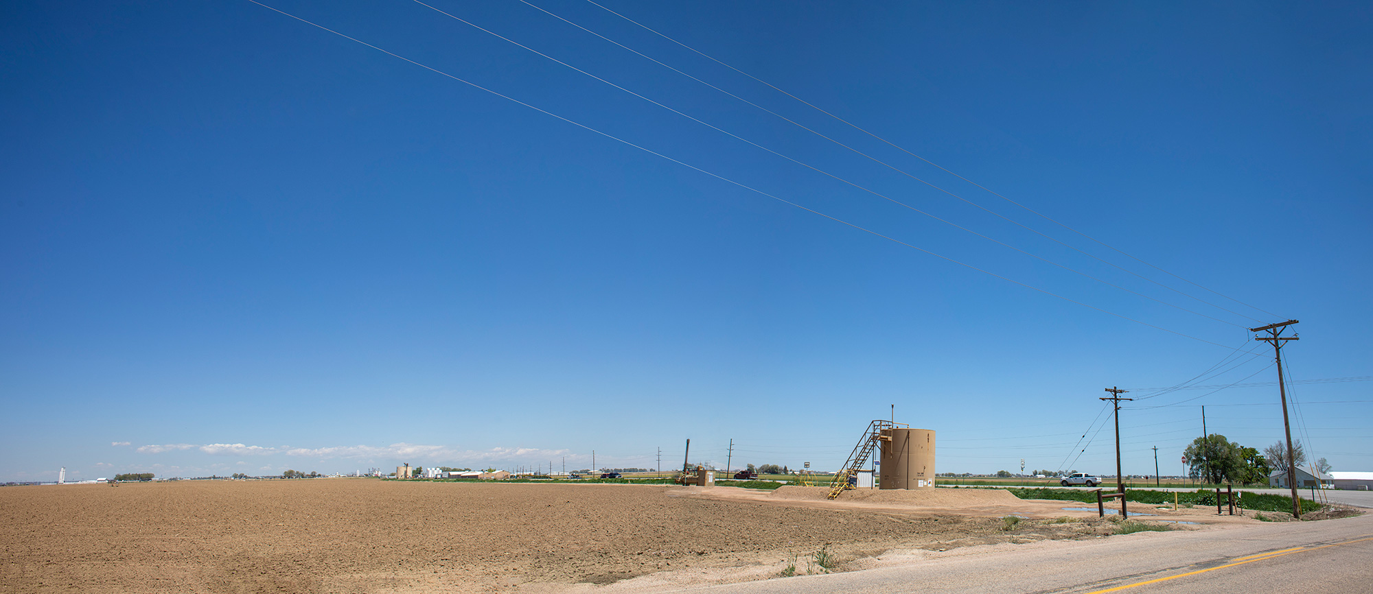
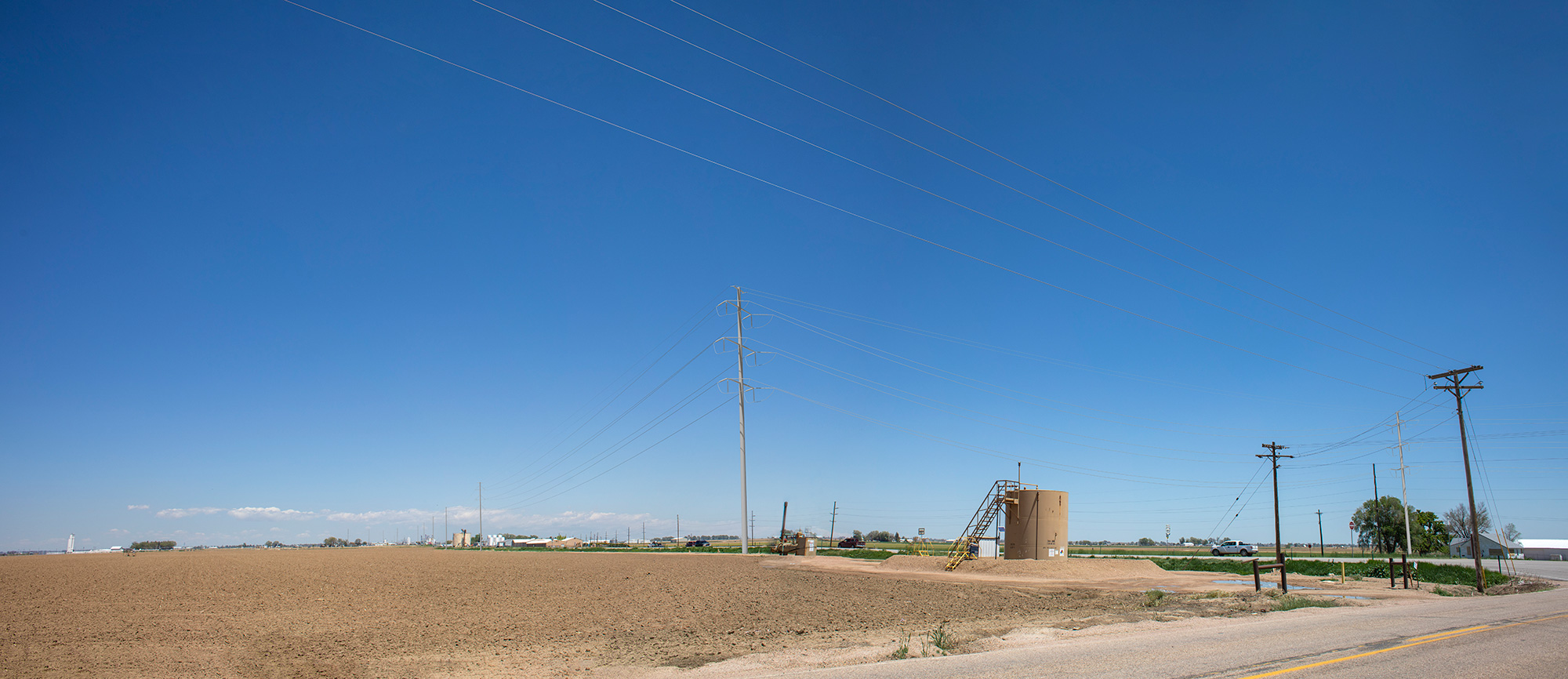
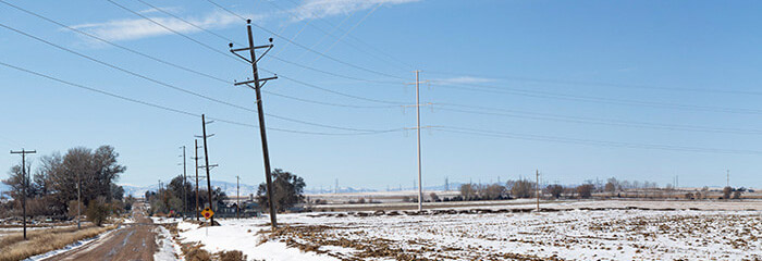
Simulation 2
28/10/2020
12:18 PM
Looking: West
County Road 84
*Photo simulations are for discussion purposes only and may change pending public, regulatory, and utility review.
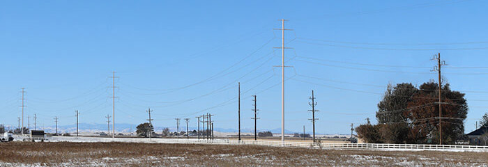
Simulation 3
28/10/2020
11:48 AM
Looking: Northwest
County Road 37 near Stark Farms neighborhood
*Photo simulations are for discussion purposes only and may change pending public, regulatory, and utility review.
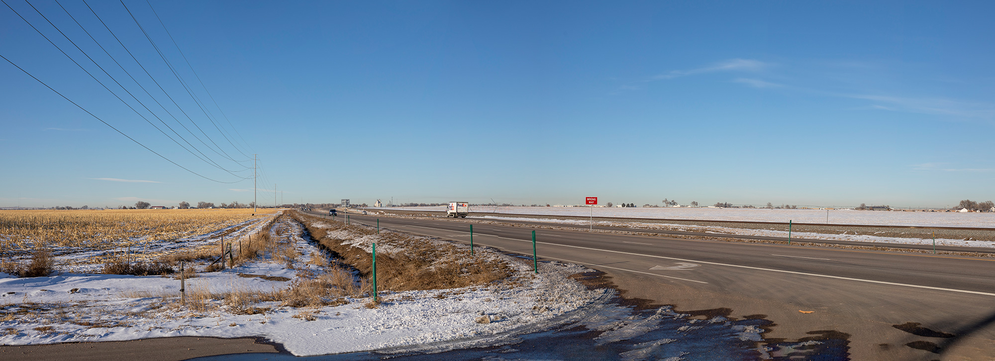
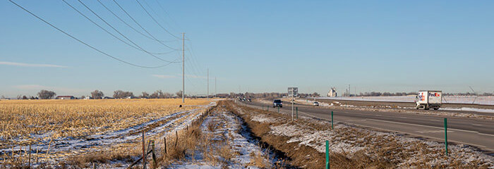
Simulation 4
17/12/2019
3:56 PM
Looking: North
US Hwy 85 at County Road 78
*Photo simulations are for discussion purposes only and may change pending public, regulatory, and utility review.
Simulation 5
02/10/2020
12:36 PM
Looking: South
Collins Street-County Road 39 intersection
*Photo simulations are for discussion purposes only and may change pending public, regulatory, and utility review.
Simulation 6
21/05/2021
2:24 PM
Looking: North
County Road 66-US Hwy 85 intersection
*Photo simulations are for discussion purposes only and may change pending public, regulatory, and utility review.
arrow_left
NCAP Photo Simulation 1 Button
NCAP Photo Simulation 2 Button
NCAP Photo Simulation 3 Button
NCAP Photo Simulation 4 Button
NCAP Photo Simulation 5 Button
NCAP Photo Simulation 6 Button
arrow_right

Public Outreach

Xcel Energy is reaching out to the public in communities crossed by the project area to inform you of construction progress and help answer questions. Please visit this website to view videos about the project, review answers to frequently asked questions, and read up-to-date project information. Additionally, during construction, Xcel Energy will periodically email newsletters and/or project updates to landowners on the email list. Click here to join the email list.

Xcel Energy maintains a telephone information line (888.678.7640) and email address (NORTHERNCOLORADO@XCELENERGY.COM) to receive questions and comments.


Northern Colorado Area Plan Infographic

Project Communications

Xcel Energy developed a comprehensive planning process that integrated public outreach and community meetings to gain public input for consideration in the planning process. A Community Working Group (CWG) was established, comprised of local citizens with diverse interests, to work with the project team throughout the planning studies.

The Xcel Energy project team reviewed public comments, land uses and environmental characteristics of the study area and developed a planning approach that considered constraints and opportunities for siting the new Collins Street Substation and routing the new 230-kV transmission line from the WAPA Ault Substation to Cloverly Tap.

Videos and materials from the public Open House meetings are available below in the “Public Open Houses and Community Working Group” accordion. Historic public outreach activities are captured in the below downloadable timeline graphic.

Contact:

northerncolorado@xcelenergy.com | 888.678.7640

    *Required field. By clicking submit, you agree to Xcel Energy’s Privacy Policy